

Introduction
Hello and welcome back yet again! Today we have a simple crackme written in Assembler. Someone I've been helping recently sent me the binary asking for help. When I originally looked at the binary I was confused because I was expecting a C/C++ binary. Only to learn later that it was written in Assembler which changed how I looked at the binary. The challenge honestly is not very difficult but I did learn a few interesting instructions so I wanted to share what I learned. Let's take a look shall we? Of course you can find the video walkthrough on my YouTube channel!
Optional Materials to Follow Along
As always, you can follow along by using my VM which has all of the tools you'll need to solve this challenge. You'll find the binary in /home/kali/reverse_engineering/crackmes/lucky_numbers. If you don't want to use my VM, you'll need to download the binary here.
Finally, you'll need a disassembler. I recommend IDA or Ghidra. I'll be using Ghidra throughout this tutorial. If you're using my VM, ghidraRun and ida64, are in the path so you can execute them from anywhere. Alright with all of that out of the way, let's get started!
Initial Triage
We start by running file on the binary as we always do!
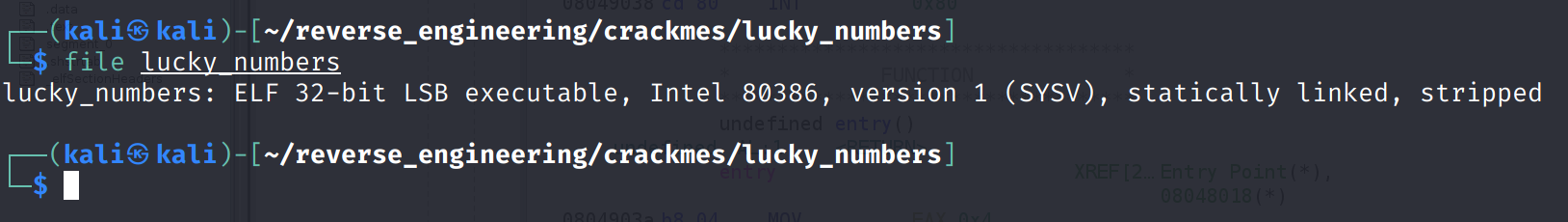
We see the binary is 32-bits and the author stripped the binary of symbols. If you're curious, as I was, here are the symbols that would be present in a simple hello_world.asm program.
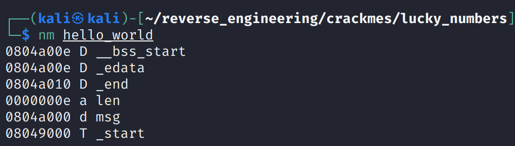
And the code that produced the binary:
global _start
section .data
   msg: db "Hello, World!",0xa
   len: equ $-msg
section .text
_start:
   mov eax, 4
   mov ebx, 1
   mov ecx, msg
   mov edx, len
   int 0x80
   mov al, 1
   mov ebx, 0
   int 0x80
Interestingly, I've never actually compiled a binary written in ASM nor have I ever analyzed one so there are quite a few firsts for me here! Anyway, let's get back on track and take a look at the strings in our target binary.
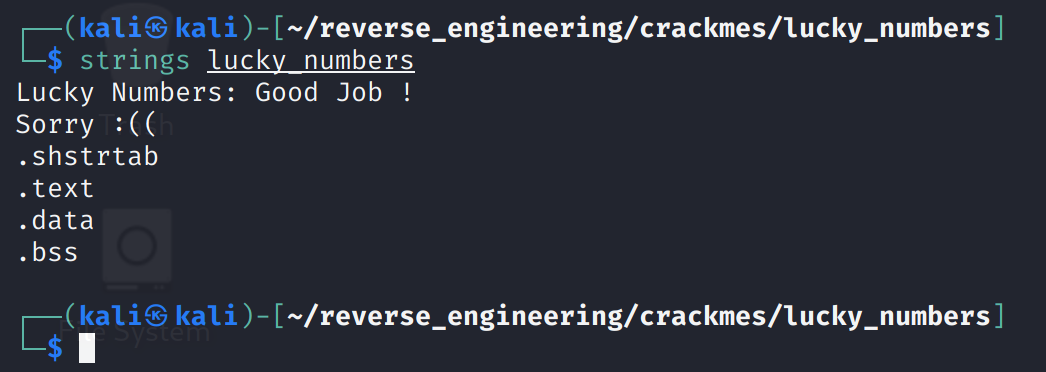
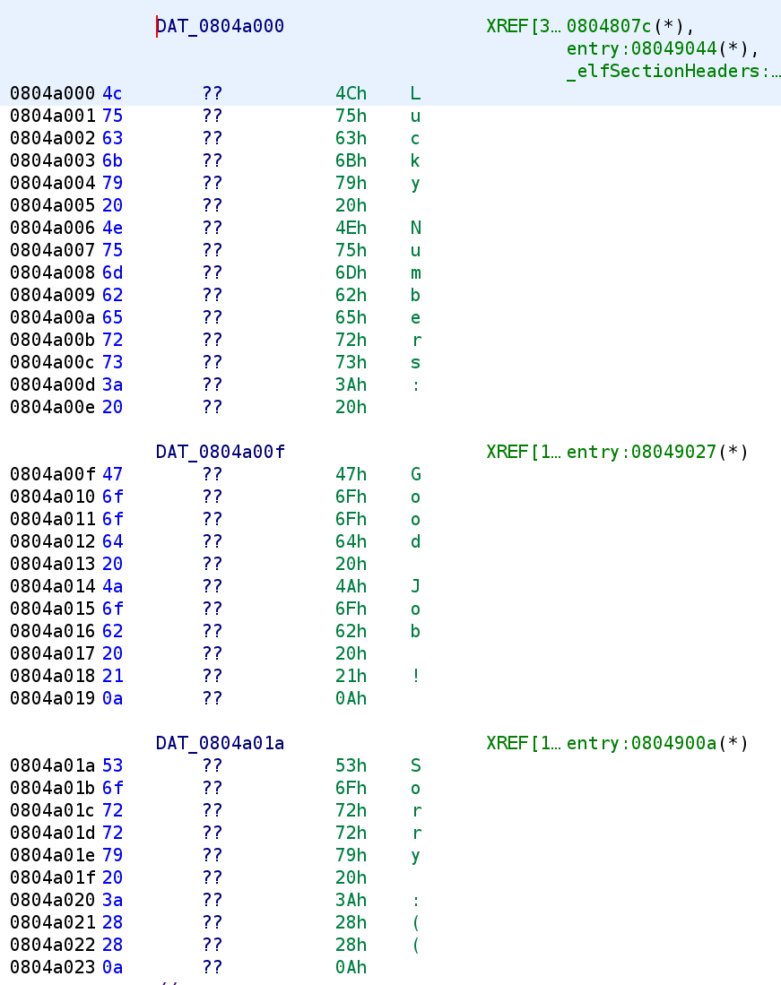
We see the normal stuff we are used to seeing. A prompt and a success and error message. Well, let's go ahead and open this binary in Ghidra!
Static Analysis in Ghidra
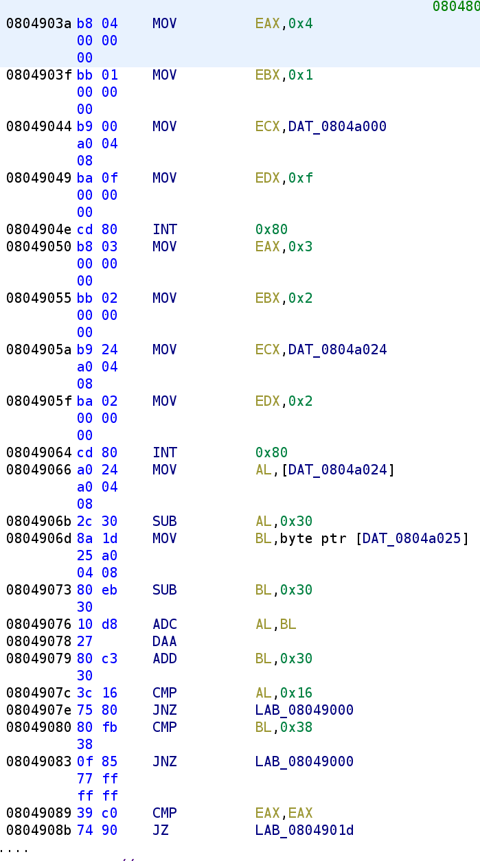
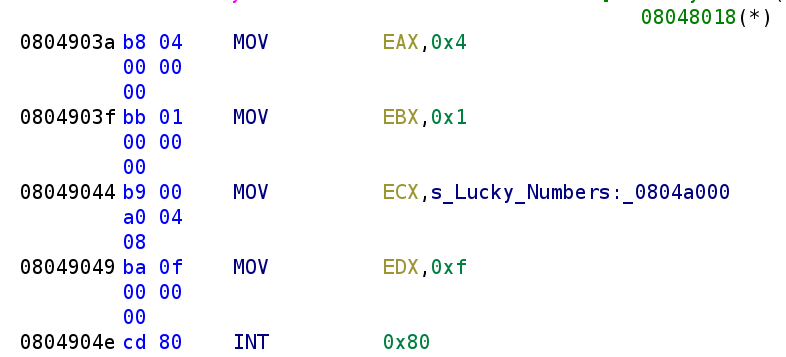
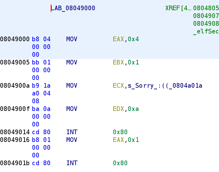
This is the majority of the binary. There are some conditional jump instructions that we'll have to analyze once we get there. But first, let's go over the first 5 lines in the binary. We see 4, 1, and 0xf are loaded in the EAX, EBX, and EDX register respectively. Further, we also see a data string get loaded into the ECX register. Before we talk about that int 0x80 instruction, let's take a look at what is stored in this data string.
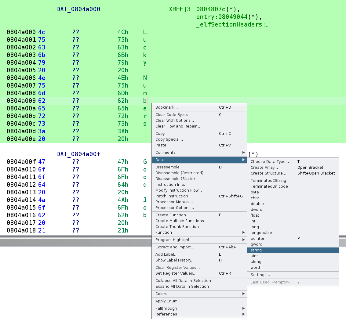
We see there were a few strings in this binary. However, this representation isn't very intuitive, so let's tell Ghidra to interpret these as strings. You'll need to highlight the entire section you want Ghidra to turn into a string, then Right-Click -> Data -> String. This is demonstrated in the image below.
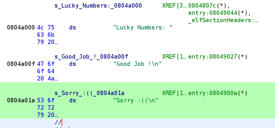
After changing the data type, it looks a lot cleaner!
What's even better is the disassembly is also updated.
Alright great! Now, what's up with that int 0x80 instruction? int stands for interrupt. What's happening in this section is the program is performing a system call. The parameters for the system call are placed in various registers. Let's take a look at the 32-bit system call table to figure out what system call is being executed and the parameters.
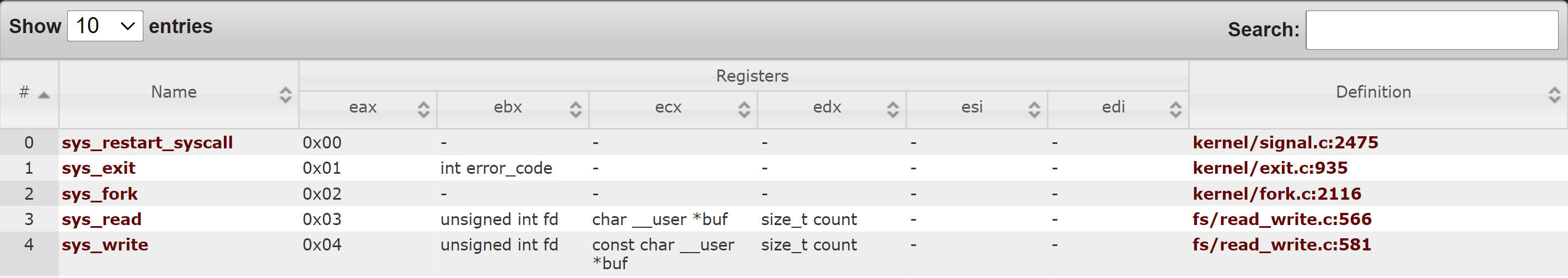
If you have trouble seeing the image above you can find a list of system calls here. It's important to remember that this is a 32-bit binary so we have to look at the system call for a 32-bit machine. There are slight differences between the system call tables. If you're curious here is the 64-bit system call table. Analyzing the table above, we see we are calling sys_write (EAX = 4) with the file descriptor of 1 (EBX = 1), the buffer is "Lucky Numbers:" (ECX = "Lucky Numbers"), and the amount of bytes to print is 0xf (EDX = 0xf). With these registers set, this is equivalent to calling printf("Lucky Numbers: "). Alright, let's continue our analysis.
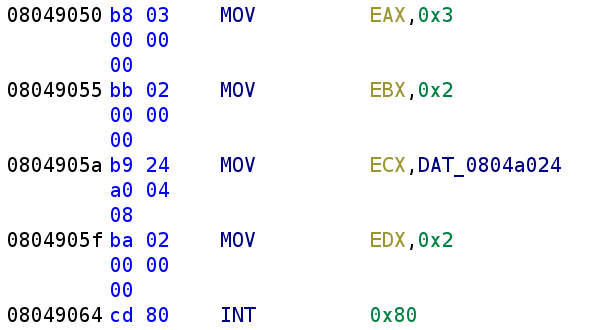
We see we have another syscall to decipher. The EAX register is being loaded with 0x3 which means this is a read. Oddly enough, the file descriptor being used here is stderr when we expect stdin. Now, I thought this was VERY odd and that there might be a problem, but I have to give a shoutout to a friend of mine from the Discord channel crackmes.one. He pointed me to the following stack overflow answer that says using 0/1/2 for input, output, and error is only a convention! You can actually use the file descriptors however you see fit. Pretty crazy right!? So, because the syscall being used is a read, let's rename DAT_0804a024 to user_input and continue our analysis.
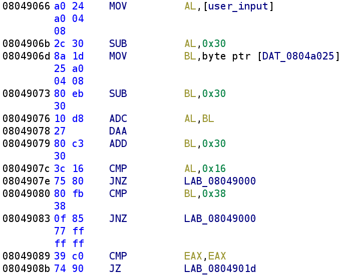
We first see the first index user_input gets stored in the AL register and then 0x30 is subtracted. So, AL = user_input[0] - 0x30. We then see the second index of our user_input (DAT_0804a025) is stored in the BL register. Similarly, BL is subtracted by 0x30. So BL = user_input[1] - 0x30. Then we see an instruction we haven't encountered before ADC. This stands for Add with Carry. This instruction simply adds the operand register, the carry flag, and the second operand to each other. So this instruction looks like this ADC -> (operand1 + CF) + operand2. The carry flag could be set in either of the two subtraction operations from before so it's important to keep that in mind when developing our solution. The next instruction, DAA, is also novel to us. This instruction confused me for a bit, but I was able to find a great tutorial that I’ll link later on. The instruction stands for Decimal Adjust AL after Addition. I know that's a mouthful!
It's important to note that this instruction ONLY acts on the AL register. No other register is affected. I know that might be obvious given the name, but I thought it necessary to explicitly point this out.There's an excellent explanation of this instruction here but I will try to explain it here. The beginning of the video is a little hard to hear but it gets really good around the 4:34 mark.
DAA Instruction Explained
This is going to be a little meaty (giggity) so I think it deserves it's own section. This instruction aims to bridge the gap between the hexadecimal numbering system used in computers and the decimal system we use in real life. What does that mean? Suppose, you are working behind a cash register and you add the numbers 88 and 88. We expect the result to be 176, however, in the computer these numbers will be treated as hexadecimal, so it will be 0x88 + 0x88 which is 0x110 (272 in decimal). Obviously, this is not the number we expect so we need a way to convert it back to decimal. That's where binary coded decimals come into play and the purpose of the DAA instruction. In the example I gave earlier, we can split up the two number (8 and 8) into two nibbles (4 bits). The higher 4 bits are called the higher nibble and the lower 4 bits are called the lower nibble. So, in this example, the higher and lower nibbles happen to be the same. But, if the number was 0x9C the higher nibble would be 9 and the lower nibble would be C. Why does this matter? Well, there are a few rules for converting these numbers back to decimal numbers. I'll explain each of these rules with practical examples!
Lower Nibble Example
The first rule I'll discuss tells us to add 06 if the lower nibble is greater than 9 OR the auxiliary carry bit is set? If you don't know what the auxiliary carry bit is, don't worry I'll be sure to explain. I never heard of it before diving deep (giggity) into this instruction. You might be wondering why do we need to add 6. Think about the problem we are trying to solve. In the decimal space, only 0–9 are valid numbers but in hexadecimal there are 5 extra characters (A, B, C, D, E, and F). You want to get the hex number back into the space of decimal digits. Since there are 5 characters we can add 6 to any of these numbers and we will fall back into the decimal digit space. Alright let's first take a look at what happens when the lower nibble is greater than 9 AFTER an addition. Let's add the hexadecimal numbers 0x14 and 0x16. First, 6 + 4 = A (10 in hexadecimal). Then, we add 1 + 1 = 2. So, the answer comes out to be 0x2A. But, remember the point of this is to convert these numbers to decimal. Since the lower nibble is greater then 9, we have to add 6 which gives us 10. The 1 gets added to 2 which gives us a final answer of 30. Which is what we would expect when we add 14 and 16 in decimal!
What The Heck is Auxiliary Carry
The other case that will cause us to add 6 to the lower nibble is if the auxiliary carry flag is set but what in the world is that!? If you already know before continuing that's impressive! Let's take the following example, 0x18 + 0x18. Hopefully the image below helps illustrate auxiliary carry. Please forgive the chicken scratch 😂.
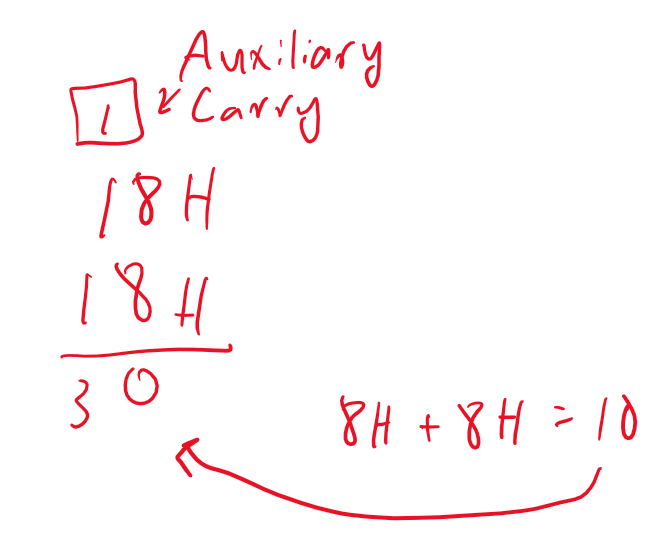
This would be similar if we were adding any two numbers whose sum is greater than or equal to 16. So, since the auxiliary carry flag would be set in this example, we add 6 to the lower nibble so our result is 36. Which is what we expect if we were to add 18 + 18 in decimal.
Higher Nibble Example
What happens if the higher nibble is greater than 9? Well in that case, we add 6 to the higher nibble. Let's look at another example: 0x52 + 0x52. Similar to what we did earlier, we add the nibbles together. So, 0x2 + 0x2 = 4. However, 0x5 + 0x5 = 0xA. Thus, making the final sum: 0xA4. Since 0xA is greater than 9, we have to add 6 to the higher nibble. 0xA + 6 = 0x10. So, the answer converted to decimal would be 104. The other case we have to deal with is if the carry flag is set as a result of the addition. Consider the following example:
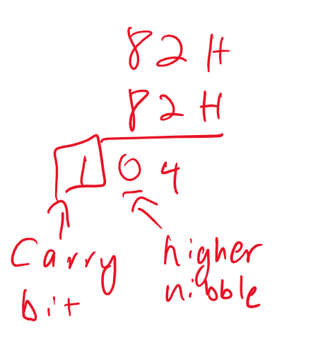
Here, we see the carry bit is the result of adding two numbers whose sum is greater than or equal to 16 in the higher bit. So, we add 6 to the higher nibble and we get 164 which is what we expect by adding 82 and 82.
Last DAA Example
Now, what happens if both the auxiliary flag AND the carry flag were set? Well, we'd add 6 to both the high and low nibbles. Let's look at one last example:
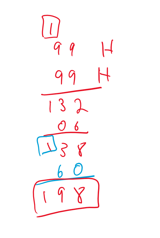
As you can see, because both the auxiliary and carry bits were set, we had to add 6 to both the lower nibble and the higher nibble in that order to get our final answer. And that's it for this instruction. I hope it made sense because it will play an important part in how we develop the solution. If not, feel free to ask me any questions. My contact information is at the bottom of this blog post right before my Patreon information😉. Alright, let's FINALLY get back to our code!
Back to the Disassembly!

Alright, nothing has changed here except we now have a deeper understanding of each of the instructions. So, after the DAA instruction executes, we add 0x30 to the BL register. Next, we compare AL with 0x16. If AL isn't equal to 0x16 we jump to LAB_08049000. Let's take a look at what this code segment does.
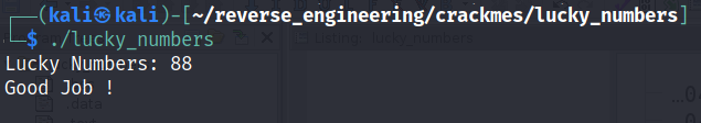
As you can see, if AL is not equal to 0x16 then we fail. The next comparison between BL and 0x38 tells us that BL should be equal to 0x38 otherwise we fail. Let's think a little what this code is doing. It takes the higher nibble and lower nibble of our input and subtracts 0x30 from both. We've seen this behavior in past challenges. The author is trying to extract the decimal number from the ASCII represented number. Remember, if we type in the number 66, the higher and lower nibbles would be represented as 0x36 which is 6 in ASCII. So, it appears the author wants the actual decimal value. Then, the author performs an add with carry of the two nibbles, performs the adjust of the higher nibble, and finally adds 0x30 to the lower nibble essentially turning it back into an ASCII represented number. So, how do we go about solving this? Well, the lower nibble never really changes right? Sure it gets subtracted by 0x30 but as we saw, 0x30 gets added back. So, the lower nibble has to be 8 otherwise BL will never be equal to 0x38. So, how do we find AL? Well, we know that eventually, it has to be equal to 0x16 after the addition and the adjustment. That means we can essentially treat 0x16 as the decimal 16. That's what the DAA instruction does after all. Converts hexadecimal numbers to binary coded decimals. Let's apply some simple algebra to solve for AL. So, our equation is AL + BL = 16 which becomes AL = 16 - BL. We know that BL has to be 8 so AL must also be 8! See, Math is useful outside of the classroom 😂. So, our solution should be 88! Let's test this out!
Conclusion
And there you have it! The most challenging part of this challenge was understanding the DAA and ADC instructions! Although it was a simple challenge I learned a lot and I hope you did as well! We learned that we can mix and match file descriptors. Additionally, we learned about binary coded decimals! As always if you have any questions feel free to hit me up on Twitter, Instagram, or Discord: jaybailey216#6540. If you have a challenge you want me to try next, let me know and I'll give it a shot! I'll see you all next time!
Peace out! ✌🏾